Earlier this semester, I got offered an opportunity to be a volunteer software engineer for a group of senior mechanical engineering students. The group of engineers were taking their senior design class in which both mechanical and industrial engineers come together to design machines to automate tasks such as manufacturing processes. The task of this particular group was to design a machine that would automate the manufacture of wire tool-heads that would be used to create designs in pottery.
Background
The project idea came from a local Duluth artist who makes pottery and pottery tools to sell on his Etsy page. These tools end up generating a lot of revenue as they are simple to make, but of much higher quality than similar tools found online. While the tools are simple enough, they are made of spring steel wire which can take a lot out of someone trying to make hundreds of tool-heads in a short amount of time. This is where the wire-bending machine comes into the picture.
Goals for this project included:
- Reduction in physical labor
- Improved production time
- Semi-autonomous design
- Ease of operation
- Programmable shape designs
There was also a provided list of constraints that had to be met:
- Total weight of machine must be less than 20 lbs.
- Machine’s base must be under 2’ x 2’ while the height of the machine must be under 1'
- Machine must be able to sit on the top of a desk or workbench
- Project budget of $400.00
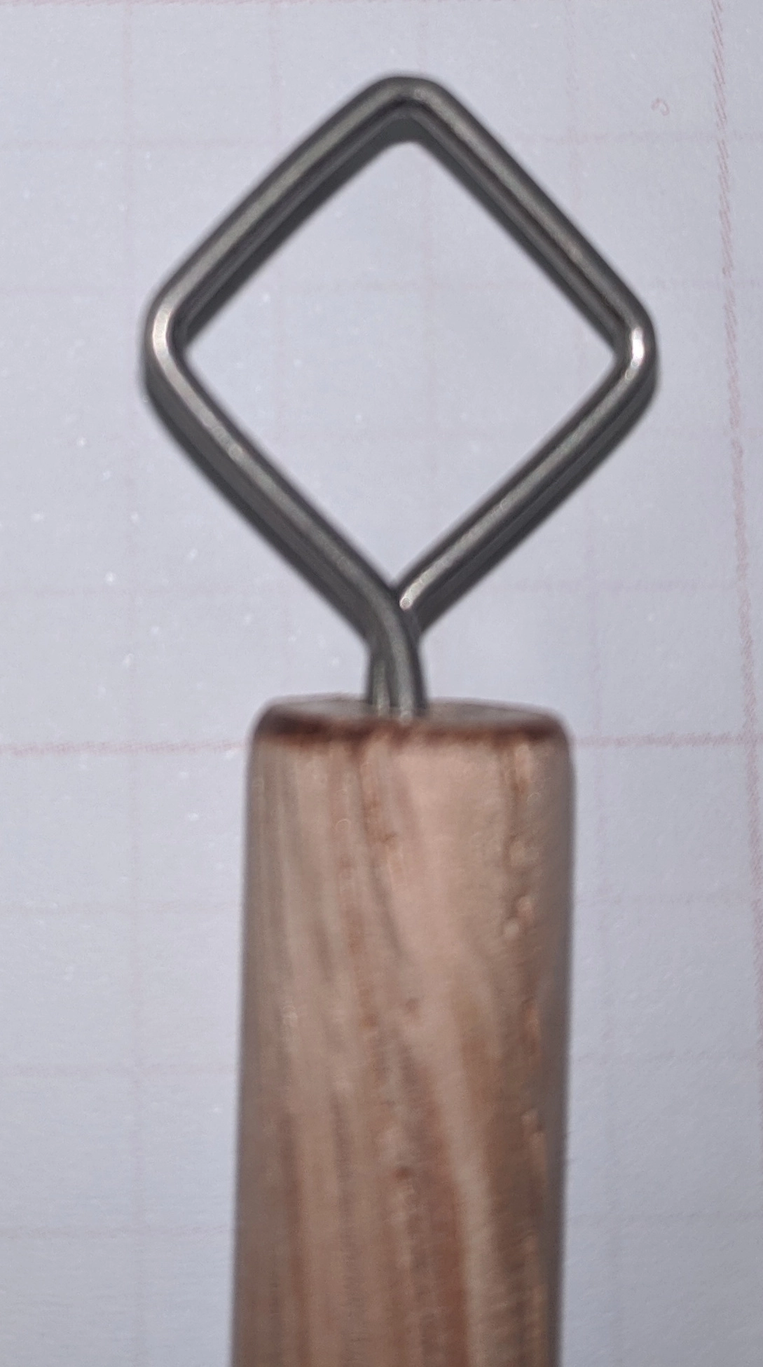
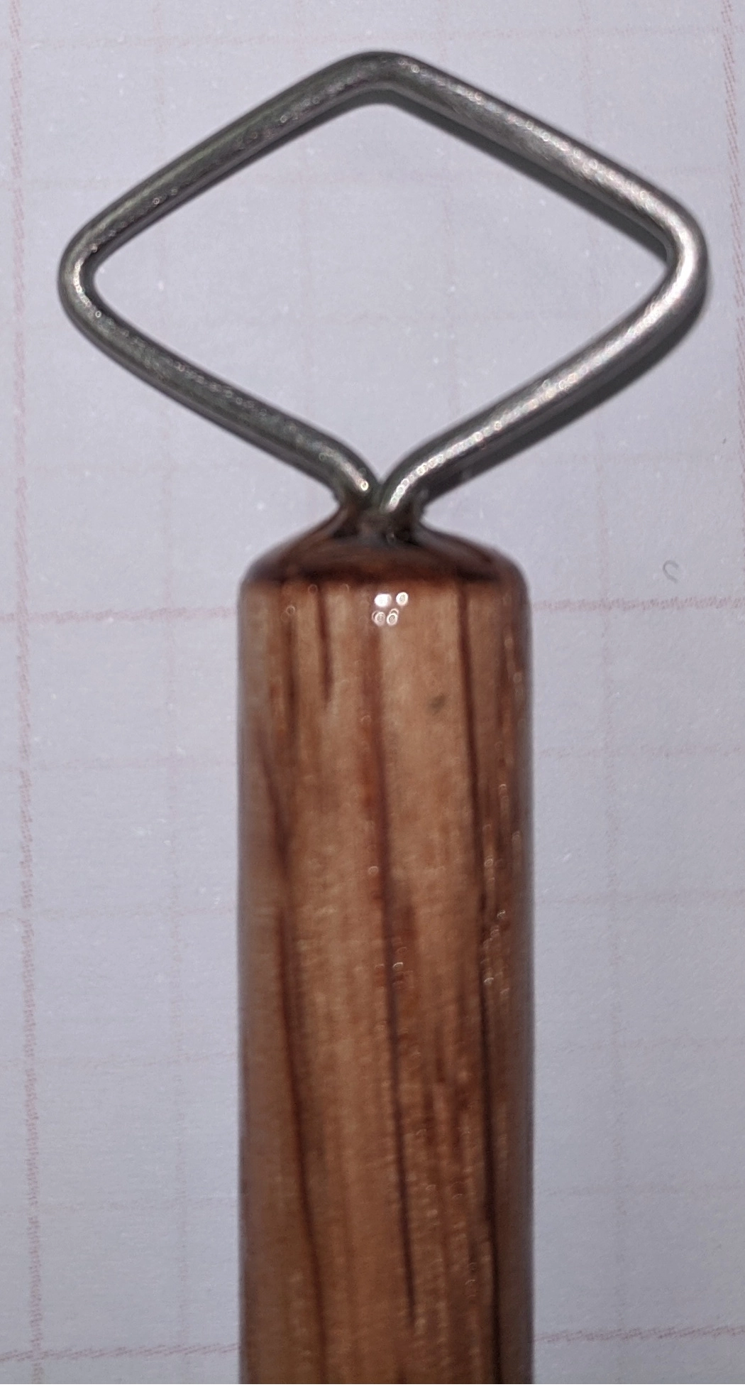
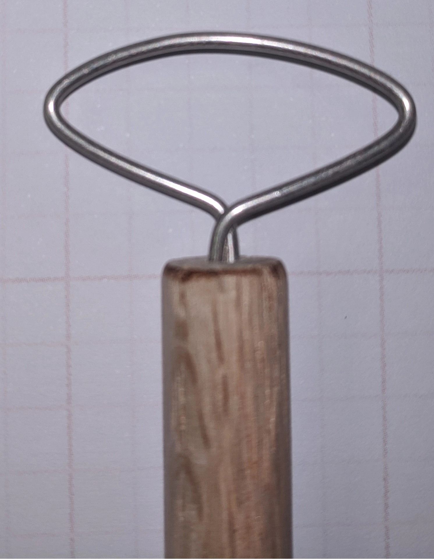
Example Tool-head Shapes
To automate the process the other engineers had already decided that they wanted to use an Arduino UNO with CNC shield to drive the stepper motors that would feed, bend, and twist the tool-heads. While I had never programmed an Arduino board before, I already knew that it was a beginner-friendly platform to program for, so I was comfortable with accepting to work on this project.
Components Used
A lot of the components used for the project were designed to be 3D printed. This would allow easy reproduction of parts that in the future may need replacement or need redesigns. The stepper motors used included a 1.26Nm motor and 2 0.45Nm motors. The larger of the three would be used to bend the wire, while the others were responsible for feeding wire and twisting wire. The larger motor helped as it had a higher holding torque compared to the smaller motors. This would help reduce the motor from slipping and keep the wire shapes consistent with each other.
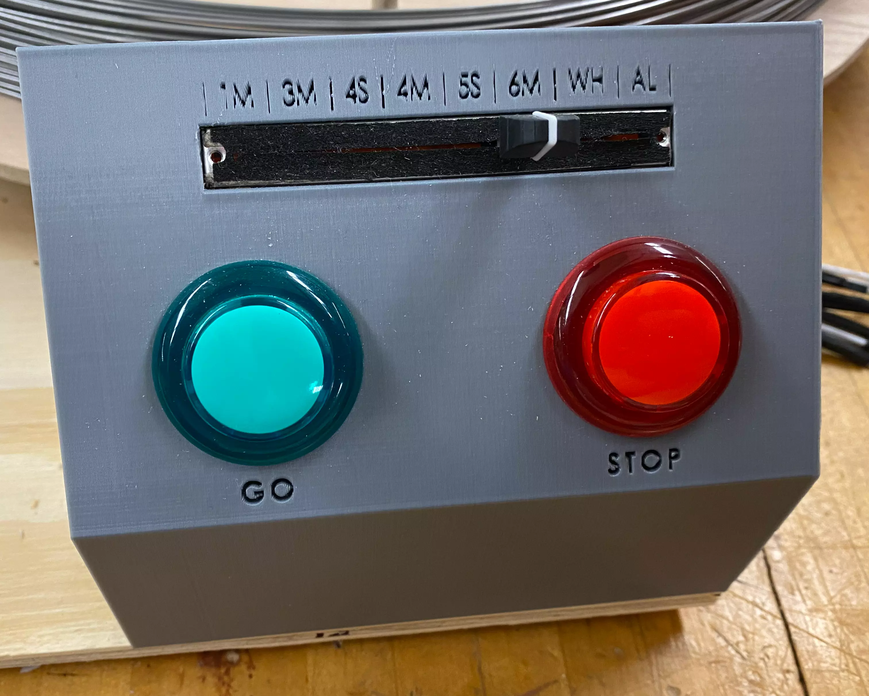
The controls used to interface with the Arduino included some LED arcade buttons and a sliding potentiometer for selecting exactly what shape the user would like to have created. To discern what part to make, the sliding potentiometer would change the current flowing through its circuit, which could be read by one of the Arduino’s analog-in pins. The main control panel had letters debossed above the slide pot so a user could slide the knob to any of the marked regions to select the desired shape.
Main Control Panel
The Code
Coding was pretty straight forward. I had seen some libraries online specially made for operating stepper motors, but I decided to skip them in favor of just writing all of my own helper functions. I figured that the code was so dependent on the design of the project such as the distance between the bend rods and the diameter of the feed wheel. Because of this, it just made sense to write my own helper functions that for example would create 90-degree bends or feed a certain amount of wire. This way I could create functions dedicated to a certain design comprised of bend functions in charge of making the specific bends necessary for the shape. Because of this, the shape functions read a lot like how someone would draw the shape.
While working on this project, I was working on a C++ project where I was tasked with documenting the entire code base. Because of this, I was learning how to configure Doxygen to generate PDF manuals and static HTML web pages describing the functions and variables of the code. This came in handy, as it helped the other engineers understand the code and how to adjust the code to fine tune the shapes.
In the future, I would like to take a look at the GRBL library so that tool-head designs can be made using a gcode editor. There’s a tutorial detailing this here.
Design Solution
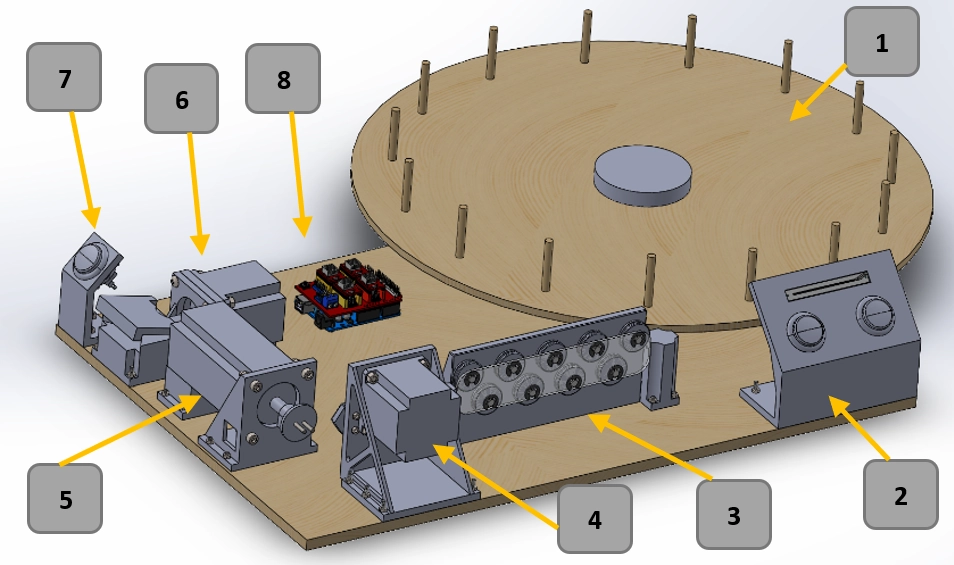
- Carousel Assembly
- Holds the spring steel wire
- Main Control Plate
- Allows user to select which design to be made
- Green button to start the process
- Red button for emergency stop and resetting the machine
- Straightener Assembly
- Removes any memory the wire would have from the spool
- Allows straight access to the wire feeder assembly
- Wire Feeder Assembly
- Pulls wire from the carousel and feeds it to the bender
- Provides additional memory removal
- Wire Bender Assembly
- Bends the wire into the selected shape
- Wire Twister Assembly
- Twists the wire ends for later insertion into handle
- Wire Twister Control Plate
- White button to start twisting process
- Arduino with CNC Shield
- Coordinates all the motors to produce the desired shape
Possible Refinement
While the client was impressed with the progress made by us in one semester, everyone involved would be lying if we said that there weren’t improvements that could be made. The bending machine is limited to certain shapes as the distance between the two bend rods limits how close tight bends can be to one another. The current distance was chosen because it increased the amount of leverage that the bend motor would have on the steel spring wire. In future iterations, this distance may be able to be shortened if more power can be delivered to the bend motor, or if another design solution increases the mechanical advantage over the wire.
Another refinement that could be made is allowing the steppers to be run simultaneously. This could decrease the amount of time it takes the machine to develop certain shapes by feeding wire while the bend motor resets to its standard position. While the code I developed gets the job done, there are libraries such as the AccelStepper library that allow for the simultaneous driving of multiple stepper motors.
Future Development
After the potter received the final product and tested it out, he was amazed by how effortlessly the machine printed out the parts (of which were difficult to discern the difference between the parts he had made by hand). Because of this and the potential to refine the machine’s design, the potter agreed to continue the development into the following Fall semester. Because of this, the professors responsible for overseeing this class asked me to be a part of the Fall 2021 senior design team that would be responsible for refining the machine, and I gladly accepted. Hopefully next Winter I will be able to give another update on the progress made on this machine!